Pages - Menu

Saturday, 16 January 2016

VIEW TOOL BAR IN CATIA V5

View tool bar is used to customize display of catia environment. In all work environments we will use this toolbar.View toolbar is common to all work environments or Modules.


Here we are having some set of options to customize the display.we will see one by one.

Fly mode:- Fly mode is used to switch between parallel projections and perspective projections.


 Fit all in:- Fit all in is used for Fit View.


   Pan:- Pan is Used to Move the Object along the linear direction 


  Rotate:- Rotate is used to Rotate the object.

  Zoom in:- Zoom in is used to Increase the zoom level of object.

  Zoom out:- Zoom out is used to Decrease the Zoom level of object.

 Normal View:- we have two applications of this option

 i)In 2D:- while drawing 2D sketch unfortunately i have used  rotate option and my work environment is disturbed.To make the sketch environment parallel to the screen we will use NORMAL VIEW option.

ii)IN 3D:- Select Normal view Option and select the reference plane you will see the view of object Normal to the selected  plane.


  Multi View:- Using the Multi View option We can see the four views of the object at a time. screen is divided into four equal parts and in each part we can see the differnt views.If want we can switch between the views also.


  Quick view:-  This is For Generating the quick possible views of the object like Front,Back,Top,Bottom,Right,Left views of the object.If you click the arrow key at quick view you will fine all these sub options.

  View Mode:- View mode is set the appearance object. if you click the arrow key of View mode you will find all sub options available.We will see one by one.

i)shading(SHD):- Object is appears with shaded material one.


ii)Shading with edges:-Object appears with shading as well as edges also highlighted.

iii) shading with edges without smooth edges:- Just like shading with edges only.addition to it smooth edges(cylinder edges,fillet edges)also highlighted.

iv)shading with edges and hidden edges:- addition to the shading with edges, it will show the hidden edges also.

v)shading with material:- The Material applied also visible in this type of appearance.
  Note: to apply material for the object click this icon , select the material and drag it on to object

vi)Wire frame(NHR):- If you activate this mode, the object appears with lines and point.

 Hide/show:- To hide or show the selected object.

 Swap visible space:-Useful when trying to find geometry hidden deep down in the tree.


This is about view tool bar in catia. If you have any doubts please mention them in coments. If you found this tutorial as useful don't forget to share it. 
Thank you..


CATIA STARTUP

By default If i want to Start any work environment in mechanical design, i should go for start--->Mechanical Design.

this is some what lengthy procedure to switch between work environments like sketcher,part design and assembly design etc.,

To avoid this drawback, we have a option to set shortcuts in 
 Catia v5. These shortcuts will appear at the startup. we can use them at any point of time to switch between work environments.

Setting startup shortcuts

i)Open catia software
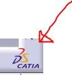
ii)Right side bottom corner you will find D S Catia symbol


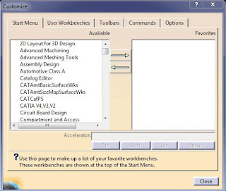
Right click On the icon--> click customize


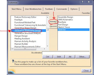
Now select the work environment in start menu and click right arrow


Repeat this process for all work environments and click close.

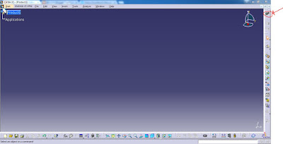
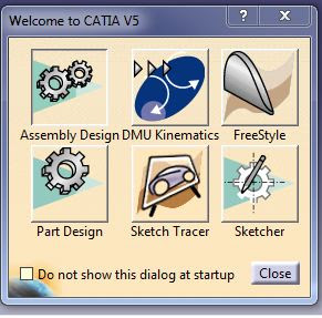
At right side top corner you will find Welcome to Catia V5 toolbar.
click this icon


Now you will observe all the shortcuts which you are added to start menu.


Using this shortcuts you can easily switch between the work environments or Modules

RESETTING TOOLBARS

If you are unable to find any Tool bar in any work environment.
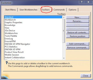
Right click on D S Catia symbol--->click customize
 Go to Toolbars


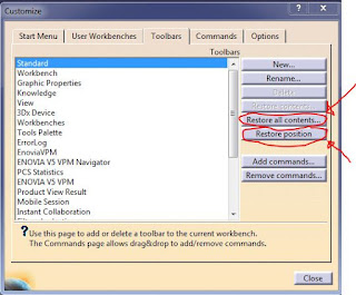
Now click Restore all contents-->ok and Restore Position-->Ok


Now click close button.

That is all about setting startup shortcuts in Catia V5.

If you have any doubts, Please Mention them in Coments.
Thank you...


Settings in CATIA V5

SETTINGS IN CATIA V5

Now we will see how to do settings in catia V5

Increasing and decreasing the size of planes
i)Open catia software
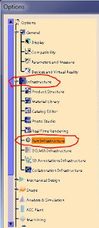
ii)goto TOOLS--->Options 


left side you will found one tree. In that goto
Infrastructure-->Part Infrastructure
Now Click on Display
Increase the axis system display size

Changing between axis system and plane system

In Catia you can do your work By using plane system or Axis system. By default Plane system is in active. If you want to switch to axis system Do the following procedure.

Select the Plane In product tree.
  Right click on selected plane-->click Hide/show

Do the same procedure for three planes.

Now click on the Axis system Icon.
by default you will find this icon at Right side Bottom corner
After clicking Axis system Icon one window will appear.Now right click on origin blank--->select create point
In point type select Coordinates.Now give x,y,z coordinates as 0,0,0. click ok


Now you Can Do your work using Axis System.

If you have any doubts please mention them in coments. 
Thank you..

Introduction to Mechanical CADD and Brief discussion about CAD/CAM/CAE.

This is a tutorial on Mechanical CADD (Computer Aided Designing and Drafting). Here you can find a very simple version of the CADD learning tutorial. This is an interactive tutorial, where youcan read the tutorials and guides and you can fire your doubts in comments section below.learn mechanical cadd

Introduction to Mechanical CADD:

The term CADD stands for COMPUTER AIDED DESIGNING  AND DRAFTING which uses a computer for the designing and drafting purposes.

In General We have Three Categories in Mechanical Cadd
  • CAD (Computer Aided Designing)
  • CAM (Computer Aided Manufacturing)
  • CAE (Computer Aided Engineering)
Now will see the importance of Each one of them

1) CAD

CAD stands for Computer aided Designing.It uses Computer Programs to create two or Three dimensional  ie., 2D or 3D graphical representations of physical objects. CAD Software may be specialized for specific applications.
In CAD softwares, based on Parametric Nature, we have 3 more sub categories. They are
  • Parametric Softwares
  • Semi-Parametric Softwares
  • Non-Parametric Softwares
Note:Parametric means the ability to change the parameters (dimensions,constraints...etc.)
we will see each one of them in detail

i) Parametric Softwares:-

While working with the software,If we can able to change the parameters at any point of time, we call it as a Parametric software.
For example, I created a sketch using sketcher environment and I converted it into 3D solid by adding some thickness in part design. Afterwards i got a need of making some modifications in sketch. If the software allows me to edit the parameters of sketch we can call it as a parametric software.
Eg: CREO parametric(PRO/Engineer),Unigraphics(Nx cad),Solid works etc.,

ii) Semi-Parametric Softwares:-

While working with the software, we are allowed to change the parameters upto certain limit. It means upto some extent only we are allowed to edit the parameters Then it is called as Semi-parametric software.
Eg:- CATIA.

iii) Non-Parametric Softwares:-

If we are not allowed to edit the parameters once we define them, the type of software is called as a Non-parametric software.
Eg:- Auto cad.

2) CAM:

CAM stands for Computer aided Manufacturing. It is for Simulating the Manufacturing Processes like Turning,Facing,Drilling etc., in the software as well as controlling the machine tools and related machinery  in the Manufacturing of work pieces.
Examples of CAM softwares are:
  • Unigraphics (NX CAD)
  • Master CAM
  • DELCAM

3) CAE:

CAE stands for Computer aided Engineering. Here it completely deals with the analysis part. analysis means predicting the behaviour of the product when it is subjected to loads and boundary conditions. In another words CAE is the usage of computer software to aid in engineering analysis tasks.
It includes Finite Element analysis (FEA), Computational Fluid dynamics (CFD), Multi body dynamics (MBD) and optimization.
Examples for CAE softwares are:
  • Ansys
  • Abacus
  • Nastron
If you have any doubts  mention them in coments. thank you...

Introduction to CATIA V5

CATIA (Computer Aided Three-Dimensional Interactive Application)  is a multi-platform CAD/CAM/CAE commercial software suite developed by the french company Dassault systems. Written in the C++ programming language.SURFACE MODELLING USING CATIA

History of CATIA

CATIA (Computer Aided Three-Dimensional Interactive Application) started as an in-house development in 1977 by French aircraft manufacturer AVIONS MARCEL DASSAULT, at that time customer of the CAD/CAM software to develop Dassault's Mirage fighter jet. It was later adopted in the aerospace, automotive, shipbuilding, and other industries.
Initially named CATI (Conception Assistee Tridimensionnelle Interactive-French for Interactive Aided three-dimensional Design), it was renamed CATIA in 1981 when Dassault created a subsidary to develop and sell the software and signed non-exclusive distribution agreement with IBM.

Versions of CATIA Software

  • The older version of this software are CATIA V3, CATIA V4.
  • Now the latest versions of the softwares are CATIA V5, CATIA V6.
In each version we are having series like CATIA V5R18, CATIA VR19 etc., here V5 indicates that Version5 and R18,R19,R20..etc., indicates the series.

Applications of CATIA in Mechanical Engineering

CATIA enables the creation of 3D parts, from 3D sketches, sheetmetal, composites, molded, forged or tooling parts up to the definition of mechanical assemblies. The software provides advanced technologies for mechanical surfacing . It provides tools to complete product definition, including functional tolerances as well as kinematics definition. CATIA provides a wide range of applications for tooling design, for both generic tooling and mold and die.

Basic Modules in CATIA V5

Module means the work Environment. In catia we are having so many modules. In our Mechanical design the Basic modules are
  • sketcher
  • part design
  • assembly design
  • drafting
  • Generative sheet metal design
  • DMU Kinematics

Advanced modules in CATIA V5

  • Wireframe and surface modelling
  • Freestyle
  • Sketch Tracer.
Now we will see one by one

1.SKETCHER

In sketcher we will Develop the Complete 2D outline of the product with the help of tools available in sketcher module.

2.PART DESIGN

In part Design we will convert 2D sketch into 3D solid by adding thickness to the sketch using the tools available in part design.

3.ASSEMBLY DESIGN

In assebly design we will assemble the individual parts using the tools available in this module to get the required component.

4.DRAFTING

It is a Technical drawing developed using the Drafting module in CATIA. It is the final output of our Design.

5.GENERATIVE SHEET METAL DESIGN

Here We will Develop the shape Using Thick Sheets with the help of tools available in Generative sheet metal Design.

6.DMU Kinematics

Here We Will Create the simulation of mechanism.mechanism will be created by adding mechanical joints like revelute joint, screw joint, gear joint..etc. using the tools available in DMU Kinematics.

ADVANCED MODULES IN CATIA V5

wire frame and surface modelling, Free style, Sketch traces comes under Advanced modules. Catia is mainly used for Surface modelling only. Here We will Create the 3D shape of the product with surfaces.
This is all about introduction to CATIA. In next page We will start with the sketcher Module. If you have any queries regarding this page mention them in coments.
Thank you...

Friday, 15 January 2016

Basics of Catia V5

Terminology in CATIA V5


The Picture is showing the Outlook of CATIA V5 software. Here we will follow some terminology
The top most bar is called as title bar and the one next to it is called as menu bar which is having all the menus like file,edit,view etc.,

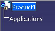
In the left side top corner we are having one option it is called as Product tree. see the picture below


The work we are Doing to develope the product will be saved in product tree only. Product tree allows us to modify and Operate the individual features of product at any point of time.

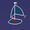
The Icon appearing at right top corner is called as COMPASS. see the picture below


We can use the compass for Panning(moving object along x,y,z axes and in planes) and rotating the 3D object. We can use this compass to recognize the current working plane also.

The Blank area appearing at right side bottom corner is called as Command line. We can work in catia using two methods.

1)Graphic user interface method: picking options directly from the toolbar using the mouse clicks

2)Command line Method: Invoking the options using the commands. we will invoke the options by typing the command of particular option in command line. remember commands is pretty easier one. just add "C:" before the name of option.
eg: if want to invoke the helix option using command line just enter "C:Helix" in command line and press enter.


Keyboard Shortcuts used in Catia v5

SHORT CUT                                  FUNCTION

1)F3                                                         -        to swich ON/OFF the Product tree
                                                              

2)Ctrl+Mouse wheel  scroll                     -        Zoom in/out the  Product tree                                                                     

3)Wheel click+Mouse right click             -       Rotating the Object

4)wheel click+Mouse right click once     -      Zoom in/out the object


5)Ctrl+ Wheel click+
forward/backfard moment of mouse         -   Zoom in/out the object

Here object refers to part,sketch,assembley or it may be any component also

We can perform all these operations using the view toolbar also, but we should know these shortcuts for fast working.